Perhaps the two most common and straight-forward requirements for precision time and frequency sources, such as quartz crystal oscillators, are frequency vs. temperature stability, and long term frequency stability which is called aging. It is always important for such devices to maintain precise frequency control over time and temperature. But in addition to these two requirements, many precision clocks need to also maintain as pure a signal as possible, over very short periods of time. In the frequency domain, this is referred to as Phase Noise. In the time domain it is measured as Jitter. There is commonality to these measurement techniques, but also important differences. While good explanations of the technical characteristics of each of these subjects are readily available, this article will attempt to explain the relationships among them and to impart an intuitive high level overview of short term stability and noise.
Phase Noise
In RF and Microwave electronics, phase noise is usually the way to look at and analyze noise. Having low phase noise frequency source is of utmost importance, because phase noise limits the ability to determine the current state and predictability of oscillators. It is good to have good frequency accuracy over time and temperature, but the purity of the signal matters too. Poor phase noise limits the amount of data that can be transmitted and received in communications systems and interferes with the most efficient use of the available bandwidth in any communications system. Radars are especially sensitive to phase noise and require the highest performance OCXOs available to limit phase noise. Traditionally, in any analog, RF or microwave application, engineers prefer to work with Phase Noise in the frequency domain.
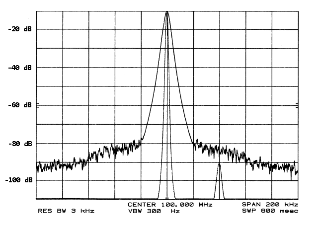
From an intuitive point of view, Phase Noise is perhaps the best way to visualize the purity of a signal. If you have a 100 MHz crystal oscillator, or other frequency signal, then you would prefer all the energy of the signal to be exactly and precisely at 100 MHz. But when looked at on a frequency analyzer that shows the output power of even the very best frequency sources, while most of the power is at 100 MHz, some power is also found at frequencies very close to the carrier (100 MHz). The further you get away from the carrier, the less noise is present. Precision quartz crystal oscillators are in fact the best low noise sources available, because quartz has the highest “Q” or Quality Factor. But in the real world, no frequency source is perfect. The amount of noise at any given offset (distance from the carrier) is given in dBc/Hz.
Keep in mind that for crystal oscillators, the phase noise is low. The dBc/Hz scale is logarithmic, so the phase noise of a good crystal oscillator, even at the closest-in offset from carrier like at 10 Hz, might be about -95 dBc/Hz, which is very, very low compared to the energy density at the carrier frequency itself, and the phase noise floor at 1 MHz and further from the carrier might be as low as -174 dBc/Hz.
Jitter
By contrast, in telecommunications industry, noise has been traditionally analyzed in the time domain using jitter. In telecommunications, which is inherently digital, jitter is the deviation from true periodicity of a periodic signal. Whereas with phase noise we are analyzing the purity of a signal in the frequency domain, with jitter we are analyzing the precision of the timing of each cycle in the square wave signal being studied.
In telecom and other digital applications, low jitter is all important in minimizing Bit Error Rate (BER). BER is a measurement of how many clock cycles will be missed over a given period of time in a digital system. Obviously, missed cycles mean missed or corrupted data.
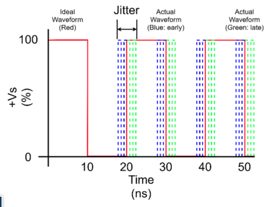
A perfect square wave signal would be exactly and precisely the same time period for every cycle. Jitter is the measurement of how close a digital timing signal comes to this timing perfection. In the telecommunications industry, the long-accepted standard has been to lock the signal of a good frequency source – usually an OCXO – to a master clock to provide very good short-term stability and very good close-in phase noise. Because the master clock would take care of any shorter term or closer in noise, the jitter, which can and is measured and characterized in many different ways, was looked upon as the integration of all phase jitter from 12 KHz to 20 MHz away from the carrier frequency. This tradition stuck and it is still the way most jitter is specified and measured.
Allan Variance
Lastly, Allan Variance is a statistical method to allow meaningful characterization of short term stability. There are a few different modifications of this in use, perhaps the most common is the Allan Deviation or ADEV. While very close in phase noise is a useful technique for examining short term stability and purity of a signal, once you get really close-in to the carrier, like for instance one second away from the carrier or even much closer in, it becomes almost impossible to accurately and precisely measure the phase noise of a single in a repeatable manner, so Allan Deviation involves making many such measurements and then taking a statistical analysis of the data set to meaningfully represent the very short term stability of a signal. The ADEV is usually used on master clock OCXOs.